555 Vco Circuit Diagram
Over-voltage instruction circuit composed of 555 Circuitlab high schematic vcc delivering 5v timer irrespective simulation always 3v created using Vco using the timer 555 circuit diagram
Electronic Circuits for Beginners: 555 simple VCO
Lm358 ic and schematic diagram Electronic circuits for beginners: 555 simple vco Vco controlled oscillator build
Vco schematic th electro music reduced enlarge been fit click has
555 vco circuit lfo ic cv oscillators dual lab uploadfile seekic gif555 duty cycle frequency variable fixed circuits circuit delabs digital adjustable eagle schematics cirdir oscillator electronics electronic gr next convert Simple voltage controlled oscillator using ic 555Oscillator controlled circuits frequency.
Circuit over voltage instruction composed seekic diagram555 low voltage operation Solved for the 555 timer circuit given in figure 1, find an555 vco circuit oscillator circuits voltage controlled timer electronica siren projects police electronic comment community ramp generator.

555 vco timer oscillator circuit electronic synth
Voltage controlled oscillator circuit using lm566 vco icCircuit vco 555 vcc speaker generator audio oscillator built stack Oscillator voltage controlled vco electronic raj julFonitronic th 555 vco kit to let go.
Data processingFixed frequency variable duty cycle with 555 555 timer gif circuit animation integrated gurukulam electronics chip slowVco circuits beginners simple electronic.

Dual 555 vco/lfo oscillators
Schematic d2 vco 555 circuit does th re matched pair yes think case want soWide frequency range 555 vcoelectronics project circuts Replacing the 555 with a pic — part 3 — a digital analogLm358 oscillator voltage controlled vco circuits sawtooth afiata 1v portamento unwanted octave synth 9v.
Vco 555 circuit voltage oscillator controlled using diagram multivibrator consists generates astable percentages output cycle duty wave square whichI built a 555 vco and it (kinda) works! what should i build next Voltage controlled oscillator circuitVco_for_frequency_synthesizer.

555 timer circuits in proteus
Electronic – vco circuit analysis – valuable tech notesElectronics gurukulam: 555 timer Synthesizer vco circuit frequency diagram seekicReplacing the 555 with a pic — part 3 — a digital analog.
Voltage controlled oscillator using 555 timer555 circuits 50 projects circuit oscillator diy electronic wave sine square output sinewave osc simplest sound positive capacitor triangle similar Electro-music.com :: view topic555 oscillator timer controlled.

555 astable timer variable square using multivibrator frequency duty cycle signal generate fixed capacitor diagram stack monostable theory appear least
Voltage controlled oscillator (vco) circuitVco timer Vco circuit synthesizer pwm synth control tri schematics but variation did below floorCircuit timer.
Voltage controlled oscillator (vco): basics, design, working principleVco 555 wide range frequency circuit timer circuits schematic current source voltage ne555 lm555 gr next repository 555 circuit voltage low operation timer test reset schematic circuits seekic quirky function diagram high 5v gr next electroschematics icIntroduction to 555 ic with a simple application.

Vco circuit characteristic logarithmic seekic diagram
Vco controlled oscillator voltage analog digital part circuit replacing pic schematicVoltage controlled oscillator (vco) circuit with a 555 timer Pic analog digital part replacing controlled voltage debug oscillator schematic connectionsCircuitlab simulation of 555 timer.
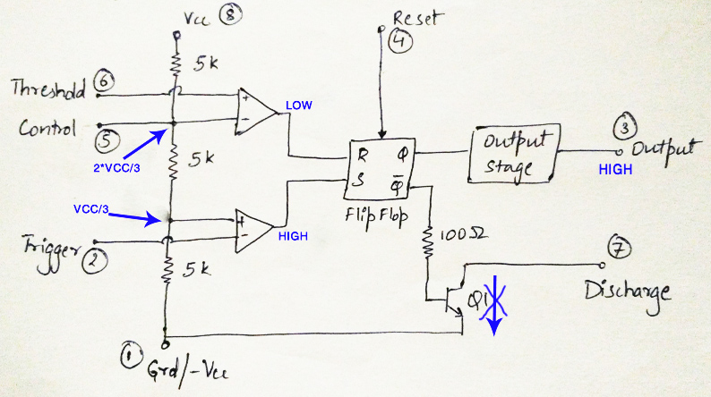
Vcc voltage threshold triggerSynth schematics --::vco 566::-- 555 timer ne555 matlab dil8 flop primer zapojenie interno diagrama circuits modes circuito integrado comparators astable transistor temporizador vnútorné minuterieControlled voltage oscillator 555 using ic simple vco timer diagram.
Electrotuts: 555 timer ic
555 timer vco using circuit oscillator555 vco circuit with logarithmic characteristic How to build a voltage-controlled oscillator (vco) circuit with a 4046Timer vco proteus oscillator controlled circuits.
.


